Hand and CAD Drawings
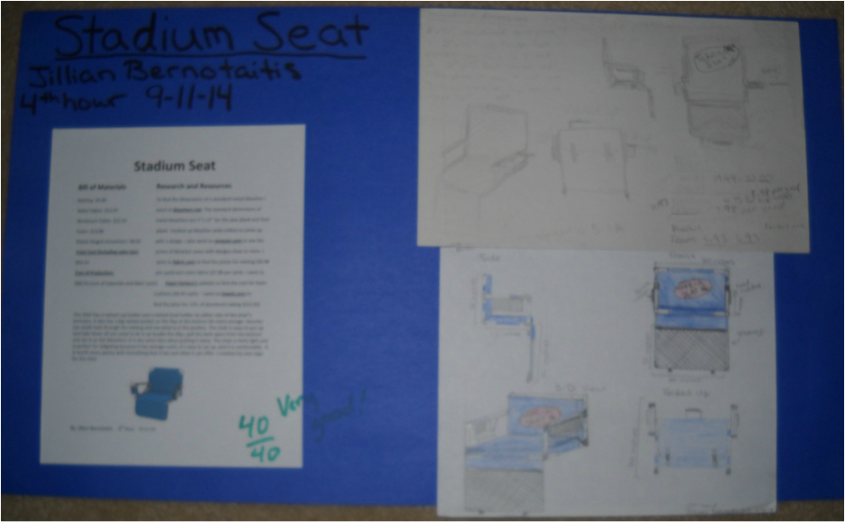
Stadium Seat Project (hand drawn)
Below is a design of a portable stadium seat. At the top left corner of the poster is the first/rough sketches of the seat. The working drawings includes a front, side, 3-D view of the seat, and a front view of the seat when it is folded up. In the bottom left corner of the poster is the final drawing. The final drawing includes a front, side, 3-D view of the seat, and front view of the seat when it is folded up. The final drawing is colored and has the logo "Take A Seat". The final drawing also includes the dimensions of the chair. On the right side of the poster is a list of materials and the cost to make one of the seats. It also describes the whole process in making the chair.
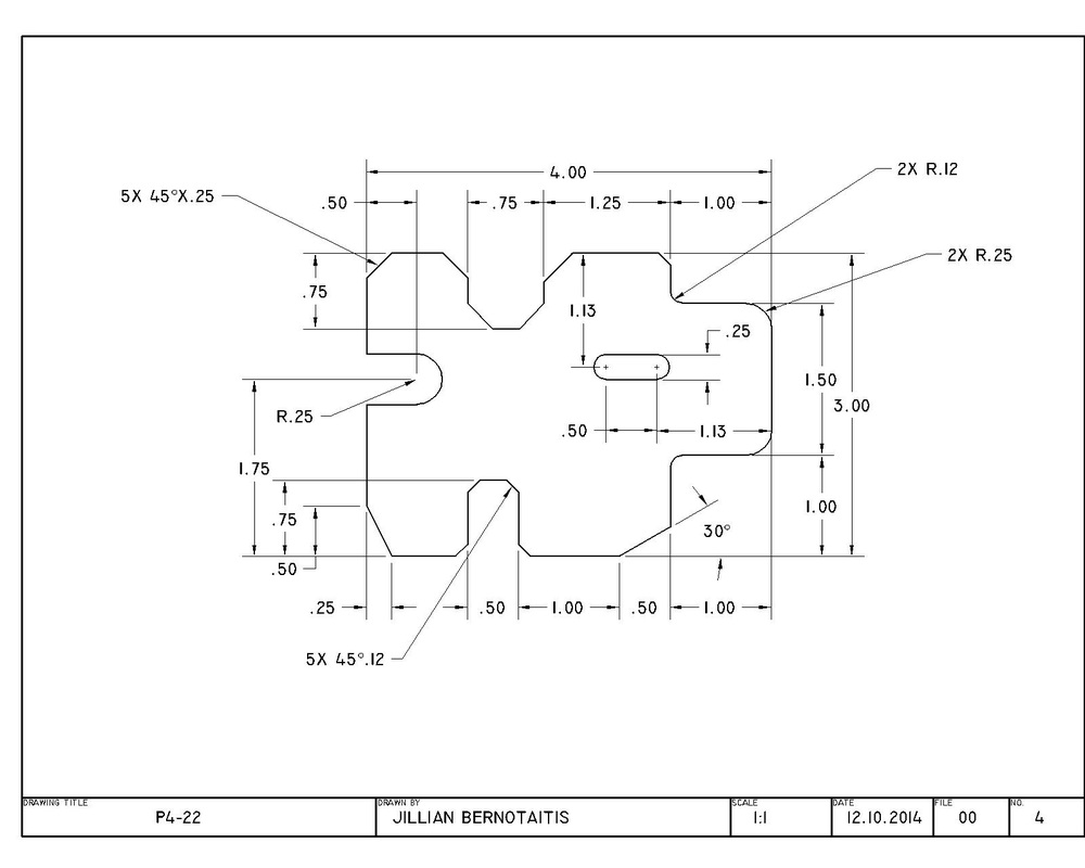
P4-22 (CAD)
Below is rectangular piece that has several fillets and chamfers (cut corners). We did this to practice the basic CAD skills.
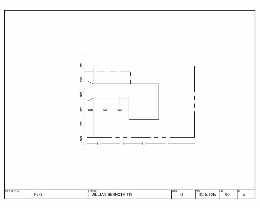
P5-8 (CAD)
Below is a drawing of a building and the gas line that goes to the building. This was used to practice making layers in CAD.
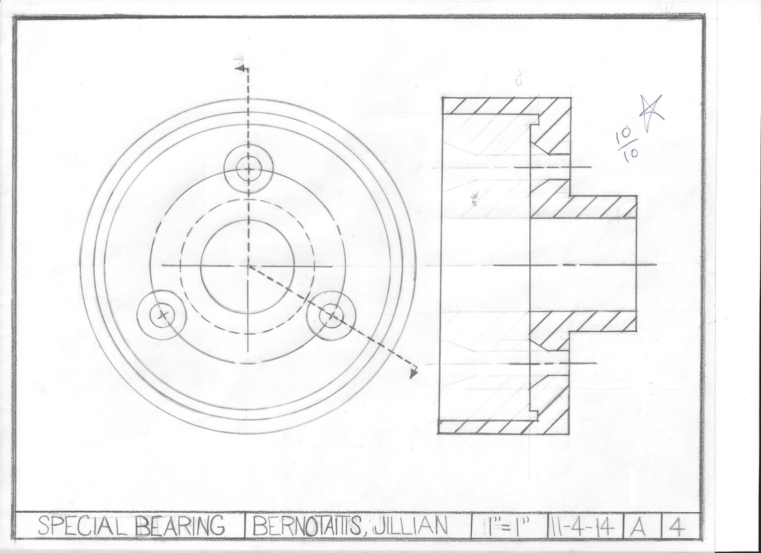
Special Bearing (hand drawn)
Below is a bearing that is pan shaped. It has 3 small holes that change their diameter half way through. The 3 small holes are around a bigger center one. The drawing has a front view and a sectioned view.
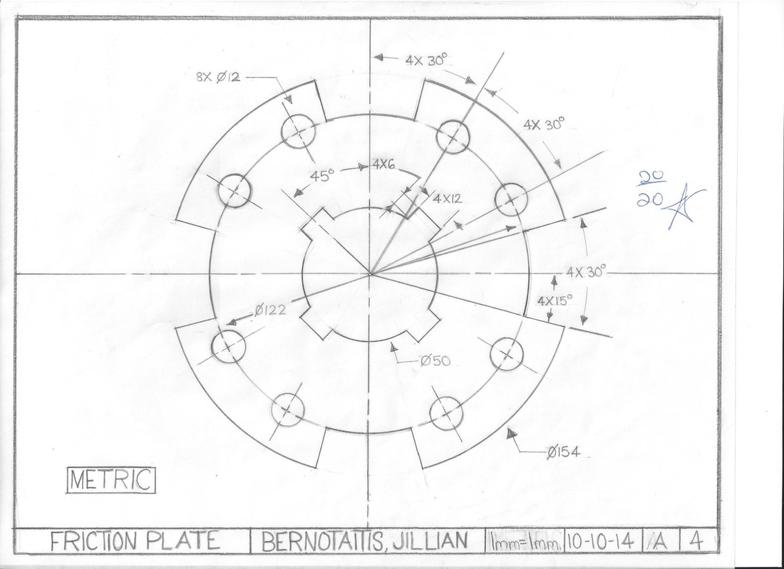
Friction Plate (hand drawn)
Below is a Friction Plate. It is circular in shape with 4 indents. There are 8 small holes that a in pairs. The medium circle in the middle has 4 evenly spaced rectangular shapes that extend from the circle. The drawing does include some dimensions and they are in metric.
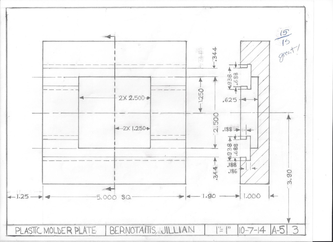
Plastic Molder Plate (hand drawn)
Below is a Plastic Molder Plate. It was one of the first hand drawing we did in class. Below is a Front and Sectioned view of the object. It is square in shape and and has another smaller square in the the center of the object. It has many indents and cliff like edges of those indents.
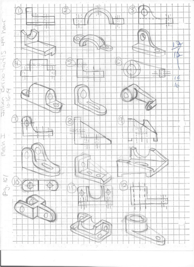
Sketches (hand drawn)
The sketches below are of different pieces of mechanical items and some unique objects. Each sketch has a 3-D view and a front view with hidden lines.
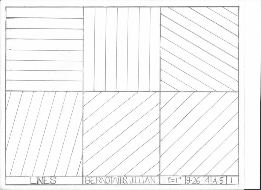
Lines 1 (hand drawn)
This was a practice using drafting tools and to learn how to hand draft. Below are several practices in drawing lines and at different angles.
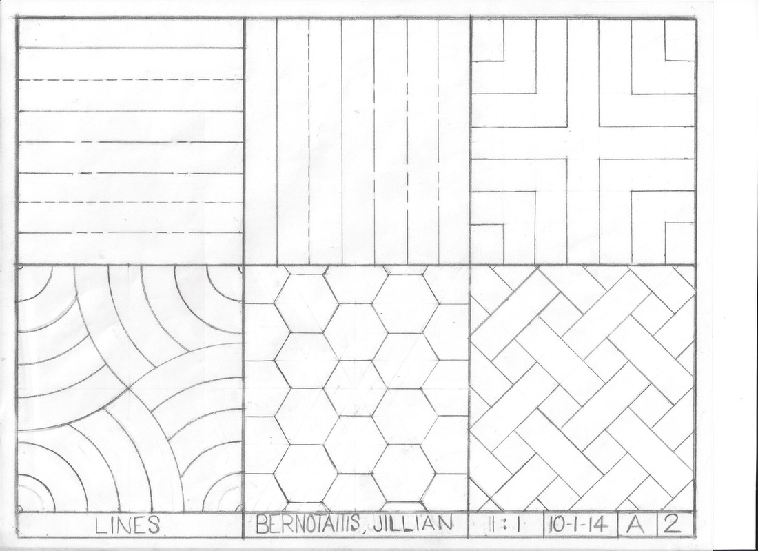
Lines 2 (hand drawn)
This was another practice using drafting tools (specifically with the compass) and to learn how to hand draft. Below are several practices with drawing different lines and drawing different complex designs.
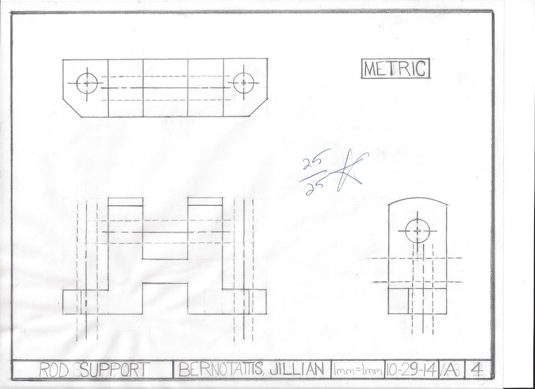
Rod Support (hand drawn)
Below are the Front, Top, and Right Side Views of a Rod Support. The piece is an "H" shape and has holes through the "pillars" and each side of its base. Each "pillar" is rounded at the top and two of its corners are cut at an angle (chamfer).
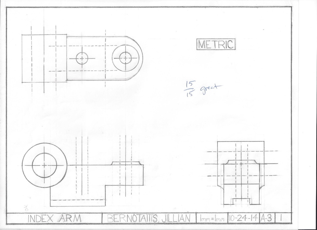
Index Arm (hand drawn)
Below is an index arm. It is rectangular in shape with some circular features. The object has 2 small holes going through the top of it. One end of the object is rounded and there is a circular elevated "plate form" where 1 of the small holes goes through. There is a lager tube that goes through the side of the object. On the bottom of the object there is an indention. The drawing includes a front, top, and right side view of the object and is drawn in metric.
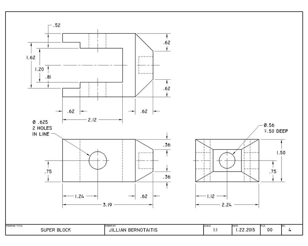
Super Block (CAD)
Below is a super block. It is a "U" shape. It has 2 hole that through the "arms" of the U and 1 hole that goes through the front of the object (the bottom of the blue). There is indents at the end of the "arms" of the "U". The edges begin to form a pyramid shape in the front, but then flattens at the hole in the front.
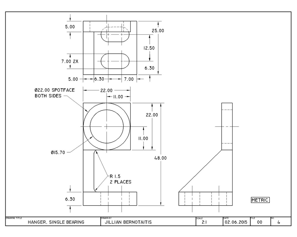
Hanger, Single Bearing (CAD)
Below is a hanger, single bearing. It is a "L"/"C" shape. The plate form that it stands on has 2 ovule like holes through it. I has a ramp like post that supports a flat square that has a big circle through it.
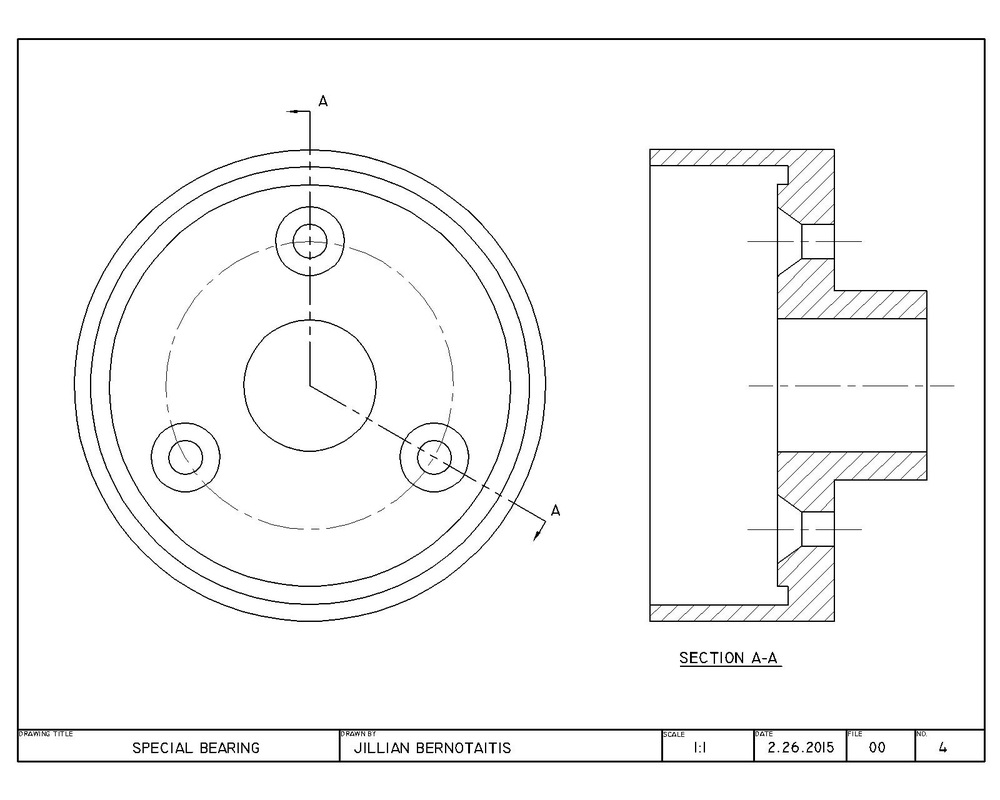
Special Bearing (CAD)
Below is a special bearing. It is a pan like shape. It has 3 small holes that diameters' get smaller at a 70 degree angle. The 3 small holes are around a bigger center one. The drawing has a front view and a sectioned view A-A.
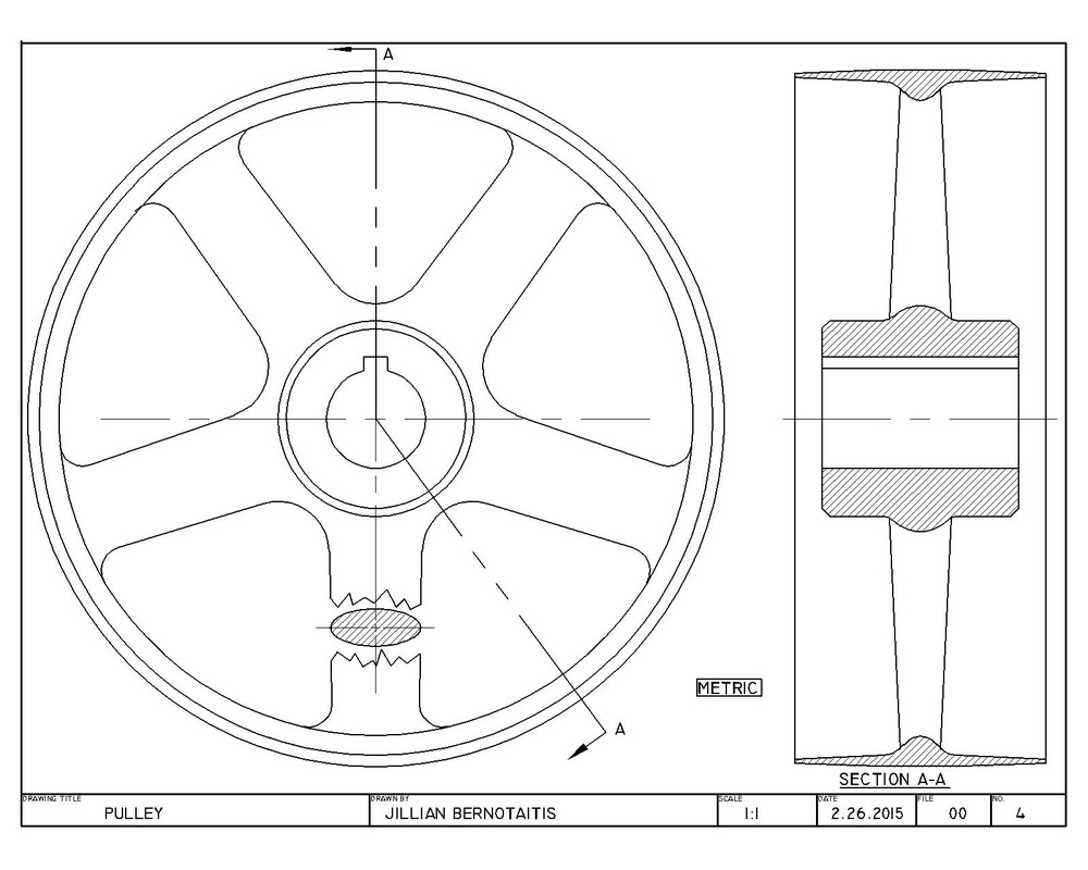
Pulley (CAD)
Below is a pulley. It is circular in shape. It resembles the spokes of a tire. It has a "key" hole going through the center of it, and has a circular tube where all the spokes attach to. Most of the edges are rounded or have fillets. The drawing below includes a front view and a section view A-A.
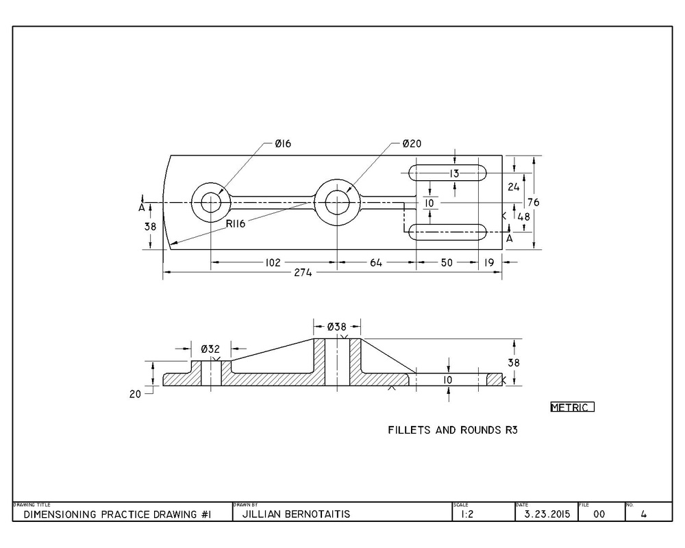
Dimensioning Practice Drawing #1 (CAD)
Below is a CAD drawing that we did not class to practice proper dimensioning. The object is rectangular shape with the left side being slightly rounded, and it has 2 circle and 2 oval holes going through it. The drawing has a front and sectioned view A-A.
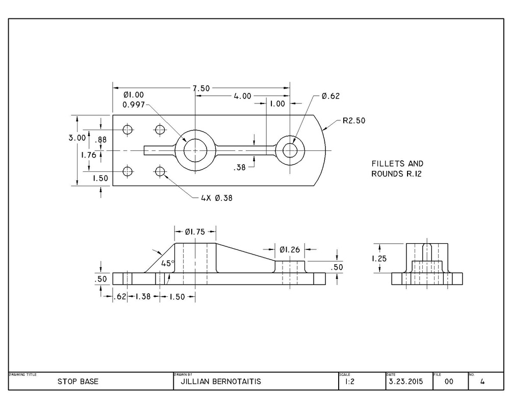
Stop Base (CAD)
Below is a drawing that we had to dimension for practice (I did not draw the actual view. I just dimensioned it.). The object is rectangular in shape and has a rounded right side. It has 4 small, 1 medium, and 1 large hole going through it. The drawing has a front, top, and right side view.
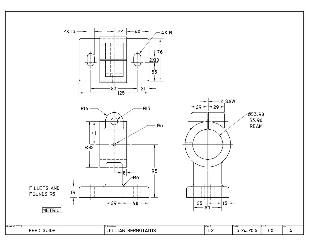
Feed Guide (CAD)
Below is a drawing that we had to dimension for practice (I did not draw the actual view. I just dimensioned it.). The base is rectangular with 2 oval holes going through it. It has a large circular hole going through it, and a small circular hole going through the top of the large hole. The drawing has a front, top, and right side view.
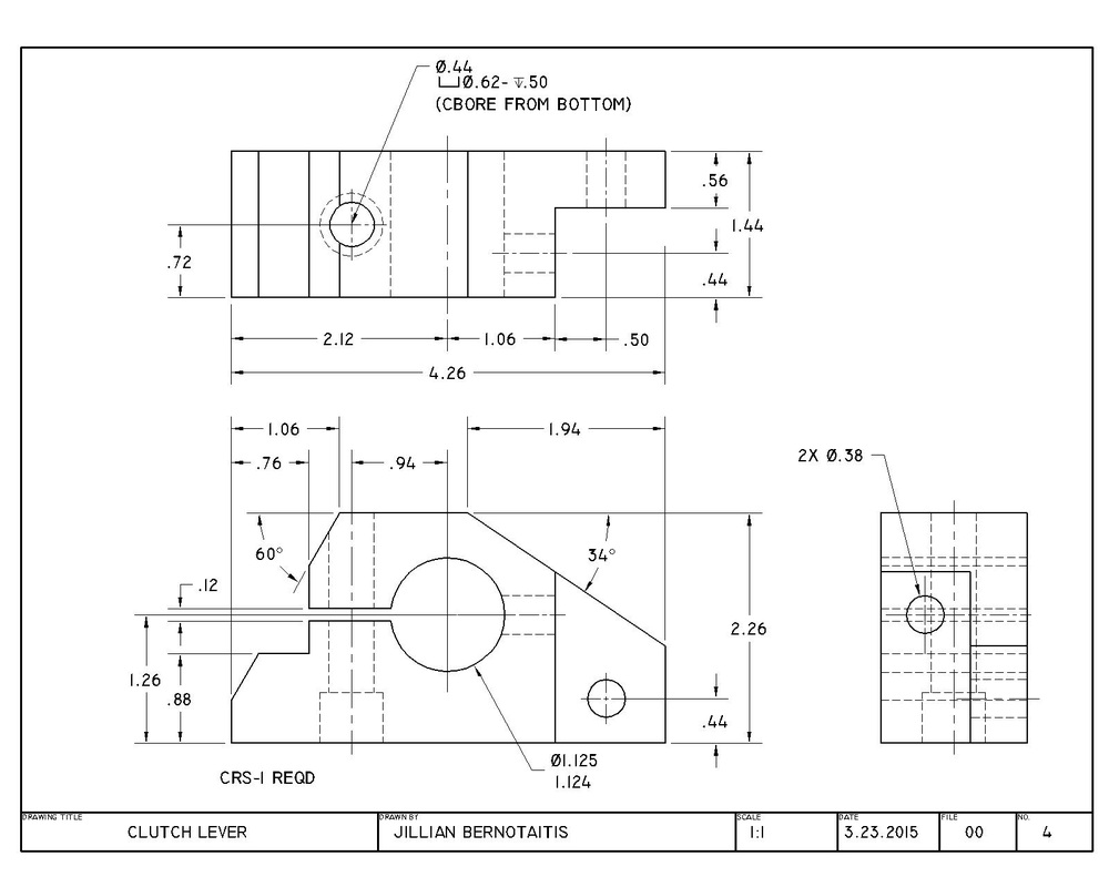
Clutch Lever (CAD)
Below is a drawing that we had to dimension for practice (I did not draw the actual view. I just dimensioned it.). It is in the shape of a trapezoid and has 3 circular holes going through the top, left and right sides. it has a large circular hole going through its front. The drawing has a front, top, and right side view.
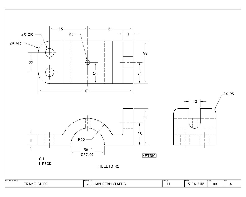
Frame Guide (CAD)
Below is a drawing that we had to draw and dimension for practice. The base is rectangular with 2 circular holes going through it. It has a large circular arch in the center of the object. A small hole going through the top of the arc. At one end of the object the the side is 41 mm tall that has a 13 mm cut out that is rounded at the end.The drawing has a front, top, and right side view.
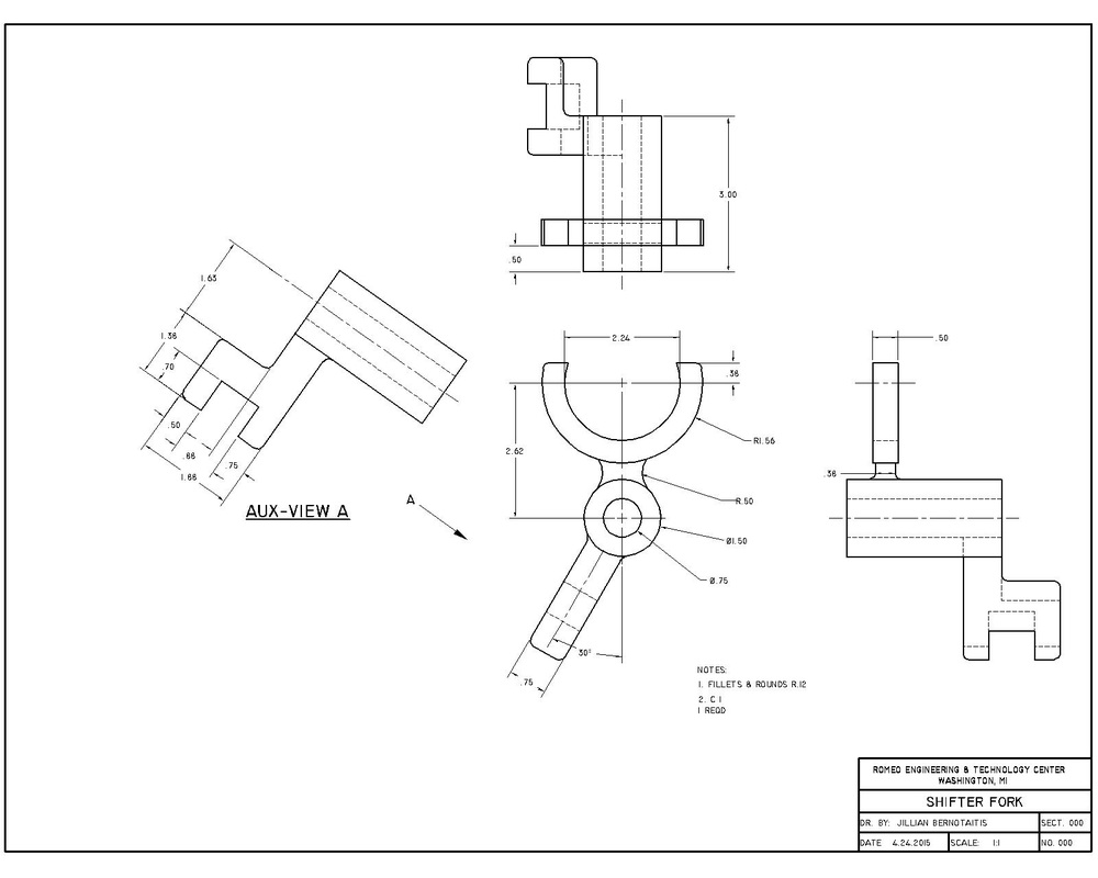
Shifter Fork (CAD) MITES
Below is a Shifter Fork for a transmission. The drawings include a front view, top view, right side view, and an auxiliary view. The object is a "U" like half circle attached to a hollow cylinder. The cylinder has a arm that extends from its bottom at a 30 degree angle. The arm is in the shape of a "h". I drew this object for the 2015 MITES competition.
MITES Engineering Log
Above is a link to my MITES Engineering Log. Everyday I worked on my MITES project, I recorded what I wanted to accomplish, everything I did, and if I was pleased with my accomplishments that day.
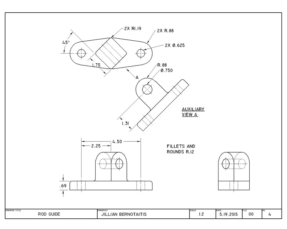
ROD GUIDE (CAD)
Below is a Rod Guide. It has an oval like base with two holes drilled through the base. It has a squared object in the center of it that has a curved top and a hole through it.. The drawing has a front, top, right side, and auxiliary view of the object. We drew this object to practice drawing auxiliary views.
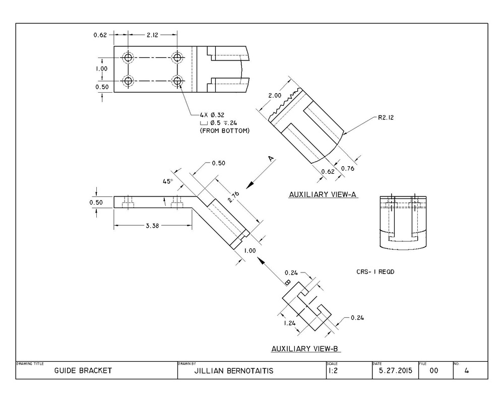
Guide Bracket (CAD)
Below is a Guide Bracket. It has a rectangular like base with four holes drilled through the base. It has a bent "side" or "arm" on its right side. The end of the bent side it a rounded/circular end. The bent end also has the center cut out partly and the edges in the inside are cut to be like "ledges". The drawing has a front, top, right side, and two auxiliary views of the object. We drew this object to practice drawing auxiliary views.