CAD
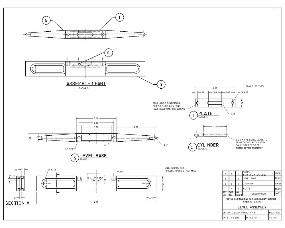
Level Assembly Drawing
Below is a drawing of a level. We drew this drawing to practice drawing assembly drawing. The level has 3 parts: a cylinder, a plate, and level base. The drawing includes a detailed drawing of each part and also a drawing of all the parts put together. The drawing also includes a parts lists for the assembly.
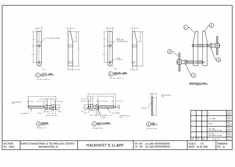
Machinist's Clamp Assembly Drawing
Below is a drawing of a machinist's clamp. This drawing was our second assembly drawing to continue to practice and master this important type of drawing. The drawing includes a detailed drawing of each part. The clamp is made up of a Right and Left Jaw, a Screw, a Pilot Screw, and two Pins. The drawing also includes an assembled drawing of the part.
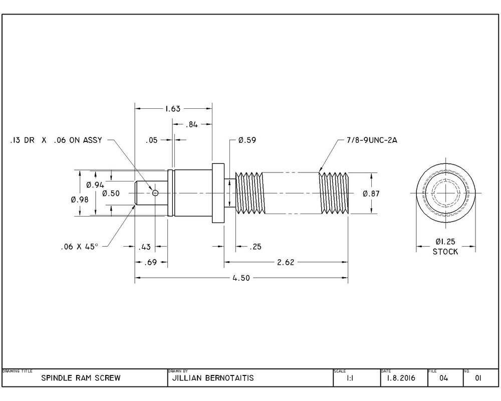
Spindle Ram Screw
Below is a drawing of a spindle ram screw. The drawing includes a front and right side views. We drew this drawing to practice drawing the threads of screws.
Inventor
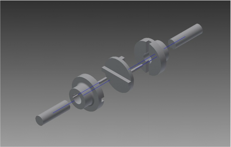
Inventor 2014- Exploded view of the Oldham Coupling assembly
Below is a 3-D drawing of a Oldham Coupling Assembly (exploded). The objects has 4 different parts and uses 3 out of the 4 twice. We are practicing using inventor in class. This is my first drawing using Inventor.
ASBE Competition
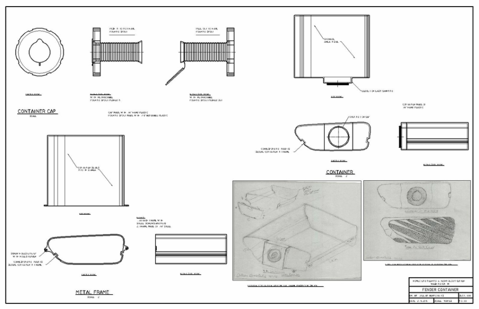
ASBE Fender Container
All the Mechanical Design classes took part in the American Society of Body Engineers (ASBE) Competition. We were given a problem to solve, and we were given about 15 days to complete our designs. The problem was a hole in the side of a the front driver's side of the car. My solution was a container that fit perfectly in the hole and could be used for either gasoline (spare gas can), water, salt (if you live in a cold area), or anything else.
ASBE Write Up
For the ASBE Competition, we had to write at least one page to explain our idea and our design process. Here is my write up for my Fender Container.
Jillian Bernotaitis
10th Grade
Romeo Engineering and Technology Center
16 February 2016
Asbe Project Design Process Essay
When I first read through and looked over the Asbe project, I began to look in detail at the car and the hole. I identified possible problems with the hole in the car’s fender. The hole could be used to store illegal things, cause structural problems in crashes, or simply look displeasing to buyers. After I had established problems with hole, I began to brainstorm possible solutions. I came up with several ideas, and it became clear that the solution would be some form of storage. I did not want to simply have a case in the hole but to have something more custom and have more of a specific purpose. I began thinking about what cars normally need and find useful. I thought of the possibility of putting a small gas can in the hole because I often see people buying small gas cans at gas stations. It seems to be a waste of money for a person to buy a small gas can every time they run out of gas at an unexpected time. I thought that it would be extremely helpful if a car had a small gas can in a safe place while still not taking up any storage in the car. I then began sketching my ideas and expressing my vision for the gas can. However, as I sketched my idea, I began to think that it would not be as useful if the container could only be used gasoline. I then brainstormed to design a container, made out of thick plastic, that could be used for not only gasoline but also for other things. The container could also be used to store water for the engine or driver or possibly salt or kitty litter if the driver got stuck in the snow. The container could also be used for anything else the driver could think to use it for. After I finalized my idea, I began again to sketch the design and represent the my vision as best I could. I drew several quick sketches of a container that was the shape of the hole and roughly 10 inches deep. The front of the container had a portion around the opening and cap of the container that extrudes which acts as a handle and way of easily pulling the container from the hole. I then sketched a special cap for the container that has a retractable spout for easy pouring if the container has gasoline, water, or another kind of liquid in it.The overall goal of my designs was to make a product that was as useful and easy to use as possible. After I designed the container, I started brainstorming ways of keeping it steady and in place while in the hole. My solution was a metal frame that would most likely be made out of steel. The frame would have holes that lined up with the ones on the right and left sides of the hole in the fender which would allow the metal frame to be attached to the car’s fender with two screws and two nuts. To secure the container even more in the frame, I designed two rectangular indents in the metal frame that ran the length of the frame. I also designed corresponding indents in the container which allowed the container to slide into the grooves of the frame and remain steady in the hole. The general idea works like a basic drawer design. After I finished my designs and drew them in CAD, I began sketching a cover for the hole. The cover would not only protect the container but also make the hole more estectly pleasing to the eye. The cover would open and function similar to the cover of the gas tank. When I was brainstorming, I came up with two designs. The first design would be a plain cover that simply blended in with the flow of the car the same way most gas tank covers do. The second idea would be a stylized fake air vent. Many cars have fake air vents now, so the idea is common but still gives the car character. The two options would be offered to buyers and would not be expensive to add or change. After I finalized my designs, I began to brainstorm the best ways to present my ideas and designs. I decided on a presentation style and completed my vision for the competition. My final design is represented by the presentation I created.
MITES Projects
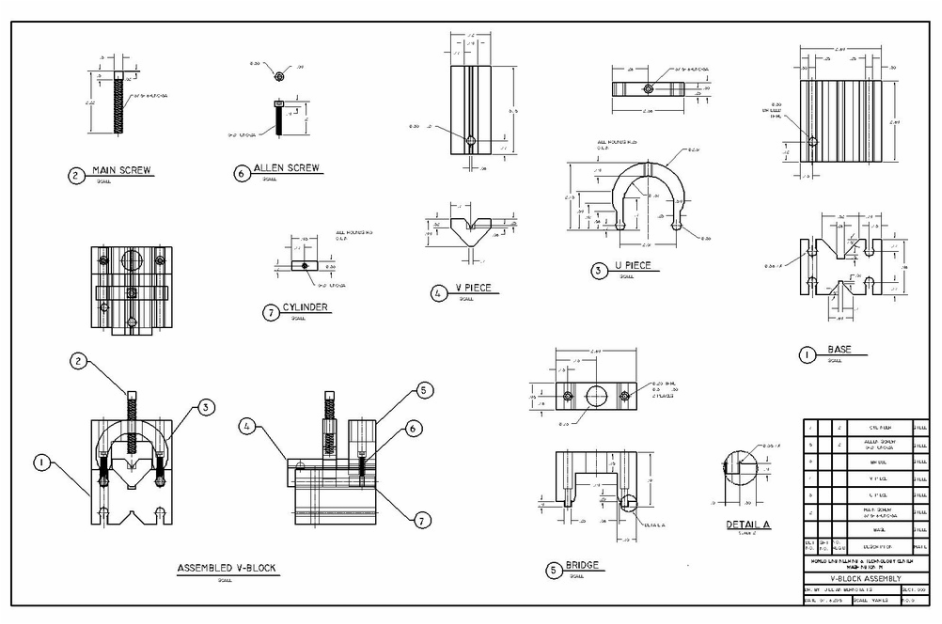
V-Block Assembly
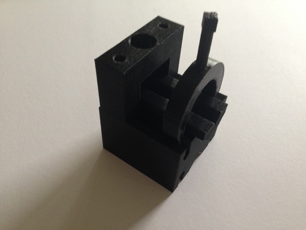
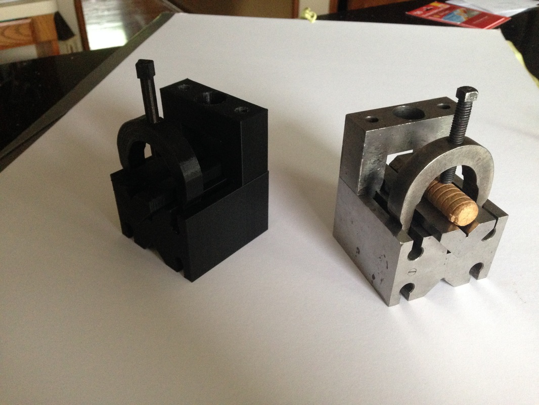
Below is an assembly of a V-Block. It is meant hold a metal rod when drilling throw or working with one. It is made up of seven different parts: a base, a bridge, a u-piece, a v-piece, two cylinders, a main screw, and two allen screws. Most of the pieces have a front and top view. The assembled drawing has a front, top, and right side view. All the pieces are made of steel.
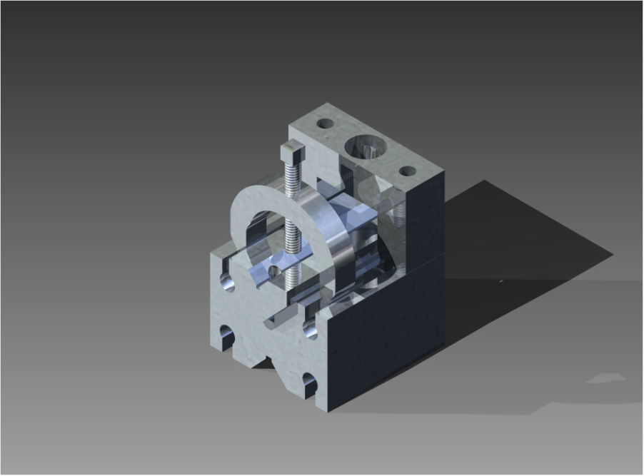
V-Block Rendering
Below is a 3-D rendering of a V-Block. I created the rendering in inventor. The V-Block is made up of seven different parts: a base, a bridge, a u-piece, a v-piece, two cylinders, a main screw, and two allen screws. All of the pieces are made of the same reflective material. The lighting is a cool blue and make the object look truly realistic.
Below it a full sized 3D printed model of the V-block that I did a assembly on.
MITES Engineering Logs
Above is a link to my MITES Engineering Log where I kept track of my progress on my MITES projects.
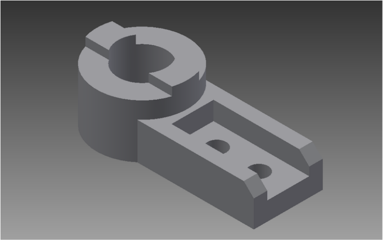
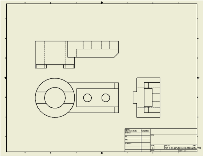
Inventor Par from Book Figure 6.81 (Level Hub)
Below is a 3D drawing in inventor of a Level Hub. It is rectangular in shape with a cylinder at one end and two smaller holes in the rectangular piece of the part. We were assigned to draw a part from the book in inventor to practice using inventor and get use to 3D drawings. I also included the orthographic drawings I made in inventor of the object.
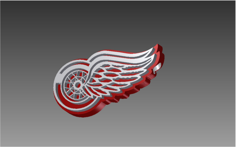
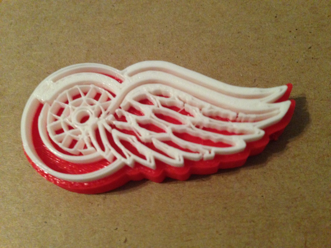
Red Wings Keychain
Below is the inventor drawing and 3D printed Red Wings keychain that I designed. We had an assignment to design a small everyday object in inventor and 3D print it. It was allow us to get use to using inventor and the 3D printers. I like the Red Wings, so I choice to make a Red Wings keychain.