Kayak Lifting Rack
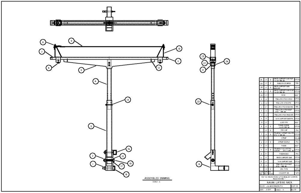
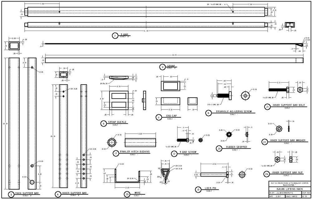
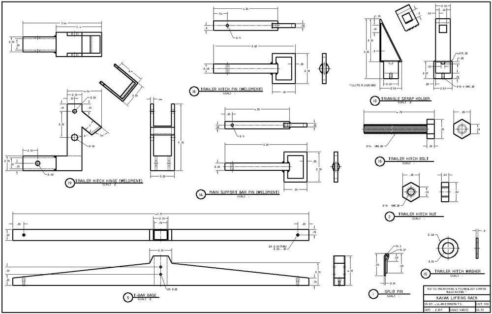
Below is an assembly drawing of a kayak lifting rack for a car. I designed and researched the kayak rack for weeks before finalising drafting it in CAD. I drew many sketches (shown below) before I decided on a final design. I modeled the design after the Rhino Rack T-Load Hitch Mount, but I made a few adjustments of my own. I was interested in doing an assembly for a Kayak rack because my family has recently began kayaking, but we often have trouble loading the kayaks. I wanted to design a solution that would make it easy for one person to kayak by themselves and load their kayak by themselves. The rack's height can be adjusted for the car of the owner, so it is very versatile.The assembly is 3 pages and includes 24 different parts.
Begining Sketches
Final Assemlby in CAD
ASBE Competition
ASBE Fuel Filler Door
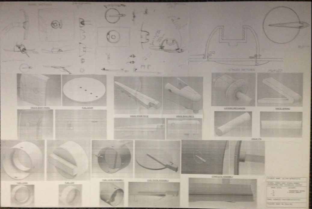
I took part in the asbe (American Society of Body Engineers) foundation High School Design Challenge. My other classmates and I were given the problem of designing a fuel filler door for a truck. We were given the fender panel and the fuel tube in the beginning. I designed many different versions until I came up with a fuel filler door with a chrome hinge on the outside of the door with a common latch locking mechanism. I wanted my fuel filler door to add a unique look to the car. I placed 3rd in the Design Concept Category.
ASBE Write Up
For the ASBE Competition, we had to write at least one page to explain our idea and our design process. Here is my write up for my fuel filler door.
Jillian Bernotaitis
11th Grade
Romeo High School
24 March 2017
ASBE Project Design Process Essay
When I was first shown the ASBE project, I first identified the problem and other issues that would come up while trying to solve the main problem. I realized that the first problem to solve would be to create an opening in the car panel, so the fuel tube could be accessed. This problem was relatively easy to solve. I would simply need to cut a hole larger than the diameter of the fuel tube in the car panel at the spot where the fuel tube lined up. After I came up with the solution for creating an opening to the fuel tube, I began brainstorming possible solutions for the actual fuel door and cap. I decided that I would make the fuel filler door unique and different while keeping the cap to the fuel tube relatively simple and functional. With my main focus on the fuel filler door, I began researching different fuel filler door designs. I wanted the fuel filler door to add style to the car, but I first needed to create a strong structure. I looked up different hinge designs for fuel filler doors and began sketching different looks and designs I liked. However, I was having trouble designing a hinge that would open wide enough to have full access to the fuel tube. I also did not like how simple and basic all the fuel filler doors and hinges looked, so I continued to sketch and research different designs. Every time I came up with a design I liked, I would soon discover an issue with it. I was beginning to get frustrated with the project. However, I continued to research and sketch different ideas, and I soon came up with a design that would solve both my problems. I was looking at an older car’s fuel filler door, but I was more focused to the chrome on the car. Then, it came to me. What if I put the hinge on the outside of the car instead of having it hidden inside the car like with most cars? If I put the hinge on the outside, it would solve my problem about making sure the door opened wide enough, and it would create a unique look for the fuel filler door. I then began sketching out my idea, and after I came to a solid design, I began to draw detailed drawings of my design. I wanted to clearly create my design on paper before I drew it in AutoCAD. As I was drawing, I brainstormed possible locking mechanisms for the fuel filler door. It took some time and research, but I eventually decided on a latch locking mechanism that most cars use. Once I had finished the detailed sketches, I began to draw my designs in Inventor. I began with the actual fuel filler door and then created the hinge parts. As I created each part of my design, I added them to different assemblies, and I eventually added them all to one assembly that was attached to the car panel. As I created my designs, I also considered the material of which they would be made. The majority of the parts would be made out of the same material of the car itself, such as steel or aluminum. The hinge of the fuel filler door would be made out of the car’s material for strength but be plated with chrome for aesthetics. The cap to the fuel tube would, however, be made out of hard plastic. After I finished drawing and creating all the parts to my design, I began to plan out how I would display my designs. I eventually decided on a poster board with all my sketches and Inventor drawings of both the individual parts and assemblies. The display I have submitted is the end result of my design process for the ASBE fuel filler door problem.
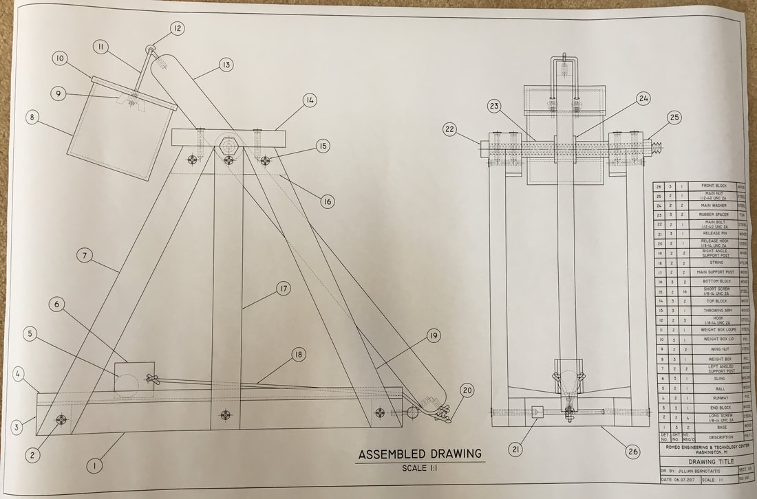
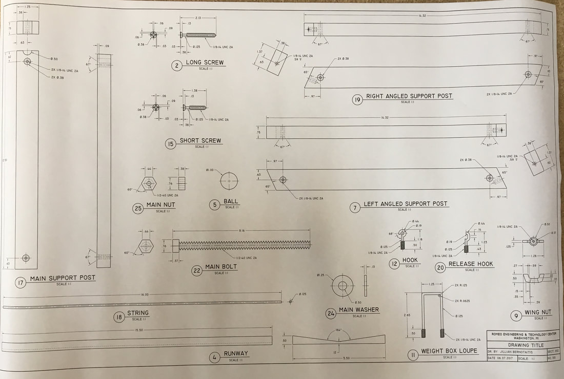
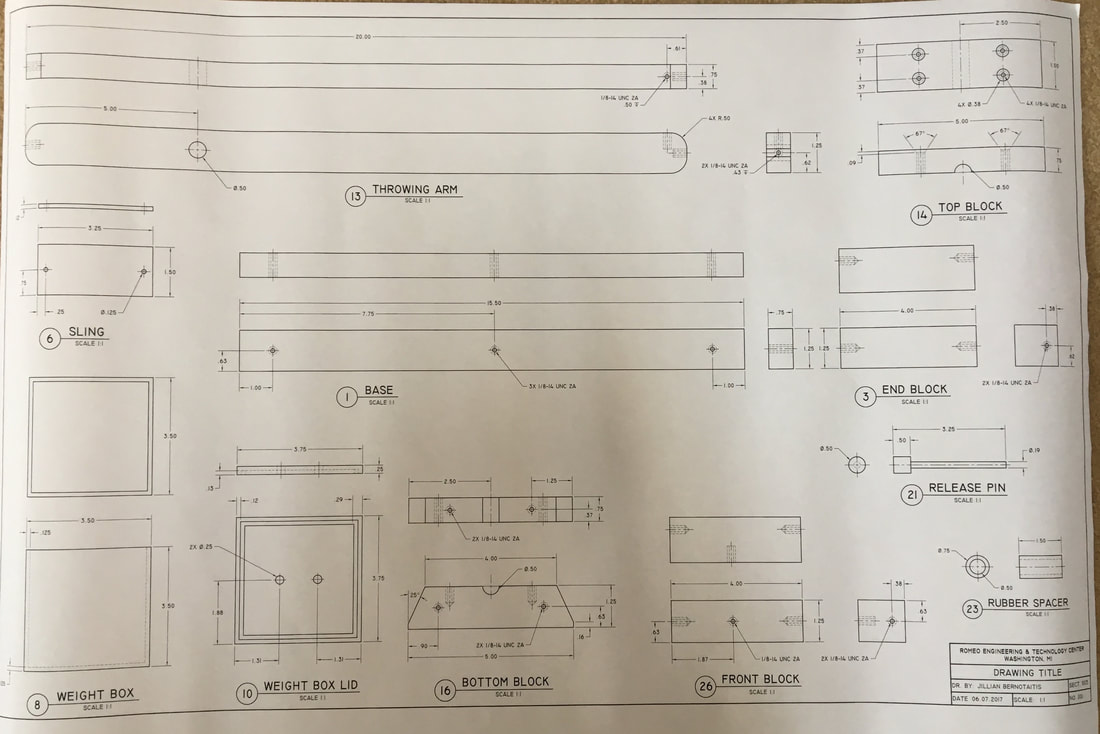
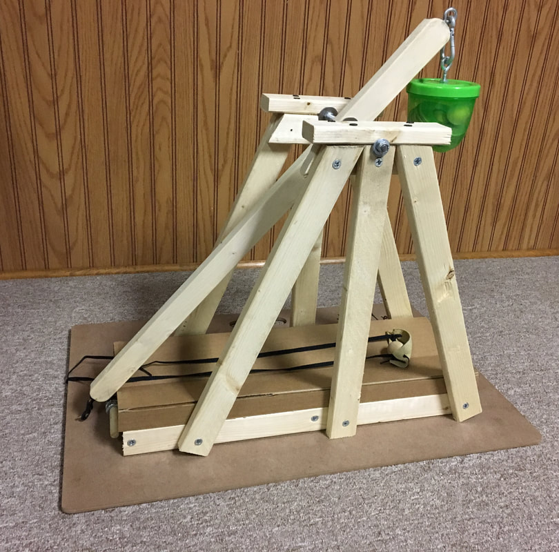
Trebuchet
Below is an assembly drawing of a trebuchet. I researched different designs and took different ideas for several different sources. I then sketched out my ideas until I came to a final design. After I had a solid design, I began to draw the individual parts of the trebuchet in AutoCAD and put them all together in an assembly. I wanted to design a trebuchet because in physics, my class learned about projectile motion, and I had to build a trebuchet for a project. I wanted to have my classes to cross over and create connections between them like it is in the work field. I drew many sketches (shown below) before I decided on a final design. The assembly is 3 pages and includes 26 different parts. I have also included a picture of the trebuchet that I built for my physics classes.